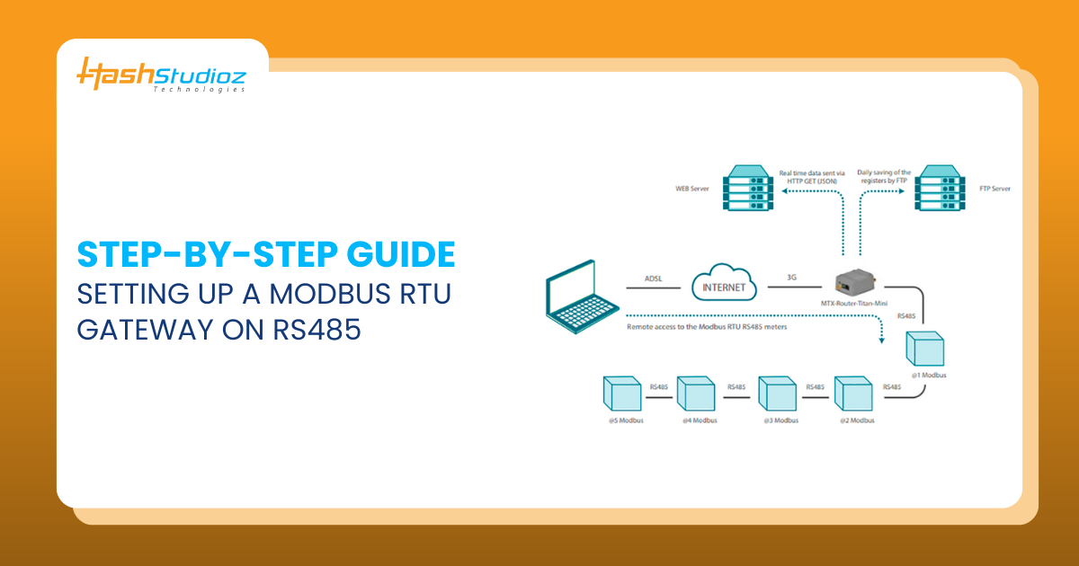
The increasing demand for industrial automation and smart systems requires seamless communication between various devices. A Modbus RTU Gateway plays a crucial role in facilitating communication between Modbus RTU devices and higher-level systems. When integrated with an RS485 IoT Gateway, it enables efficient, reliable, and scalable data transmission in industrial environments.
- Over 60% of industrial automation systems use Modbus RTU for communication.
- RS485 allows communication over 1200 meters with minimal signal degradation.
- The adoption of RS485 IoT Gateways has increased by 35% due to Industry 4.0 demands.
- Modbus RTU Gateways reduce integration time by 50% compared to traditional serial communication methods.
Table of Contents
Understanding Modbus RTU Gateway and RS485 IoT Gateway
Industrial automation and data acquisition systems often involve multiple devices communicating over different protocols. This is where Modbus RTU Gateways and RS485 IoT Gateways play a critical role in ensuring seamless connectivity between legacy industrial equipment and modern IoT platforms.
What is a Modbus RTU Gateway?
A Modbus RTU Gateway is a specialized device that translates Modbus RTU (Remote Terminal Unit) protocol into other communication protocols such as:
- Modbus TCP/IP – for Ethernet-based networks.
- MQTT – for IoT and cloud-based applications.
- REST APIs – for integration with web-based services.
By acting as a protocol bridge, a Modbus RTU Gateway allows traditional Modbus RTU slave devices (such as sensors, meters, and PLCs) to communicate with SCADA systems, cloud platforms, and modern industrial controllers.
What is an RS485 IoT Gateway?
An RS485 IoT Gateway is designed to facilitate the connection of RS485-based industrial devices with IoT platforms, cloud applications, or centralized monitoring systems. It enables:
- Remote monitoring and data collection from industrial sensors and controllers.
- Secure transmission of industrial data to cloud servers for analytics.
- Predictive maintenance by gathering and analyzing real-time device data.
RS485 IoT Gateways support various wireless and wired communication protocols such as Wi-Fi, LoRa, 4G/5G, and Ethernet to ensure seamless integration with modern digital infrastructure.
Importance of Using a Gateway in Industrial Networks
Implementing Modbus RTU Gateways and RS485 IoT Gateways in industrial networks offers several advantages:
- Bridges Legacy Equipment with IoT – Many industrial machines still operate on RS485 and Modbus RTU. A gateway enables their integration with cloud-based applications and smart systems.
- Enables Real-Time Monitoring & Data Collection – Industrial processes require continuous monitoring. Gateways allow real-time data acquisition from RS485-based sensors, PLCs, and other control devices.
- Enhances Security & Reduces Network Downtime – With features like firewalls, authentication, and encryption, gateways protect industrial networks from cyber threats.
- Supports Large-Scale Industrial Automation – Gateways allow centralized data collection and remote control of thousands of connected devices in manufacturing plants, energy grids, and smart cities.
By leveraging Modbus RTU Gateways and RS485 IoT Gateways, industries can enhance operational efficiency, reduce downtime, and optimize automation workflows.
Essential Components for Setting Up a Modbus RTU Gateway
Before beginning the setup process, it’s crucial to gather all the necessary hardware and software components to ensure a smooth and efficient installation. The following are the key components required for setting up a Modbus RTU Gateway on an RS485 network:

1. Modbus RTU Gateway
A Modbus RTU Gateway is the core component of the setup, responsible for translating Modbus RTU (serial communication) into other protocols such as Modbus TCP, MQTT, or cloud-based platforms. Ensure that the gateway you choose supports:
- RS485 serial communication
- Multiple protocol conversion (RTU ↔ TCP/IP, RTU ↔ MQTT, etc.)
- Stable industrial-grade performance
2. RS485 IoT Gateway (if required for IoT integration)
If your application involves cloud connectivity or remote monitoring, an RS485 IoT Gateway is necessary. This device extends the functionality of Modbus RTU by enabling wireless communication via Wi-Fi, LoRa, 4G/5G, or Ethernet.
3. RS485-Compatible Devices
The end devices that will communicate over the RS485 network must support Modbus RTU protocol. These devices include:
- PLCs (Programmable Logic Controllers) – Used for automation control.
- Sensors (Temperature, Pressure, Humidity, etc.) – Collect real-time data from industrial environments.
- Actuators (Motors, Valves, Relays, etc.) – Perform mechanical operations based on received commands.
Each RS485 device must have a unique Modbus ID assigned for proper communication.
4. RS485 Communication Cables
RS485 communication requires shielded twisted-pair cables to minimize electromagnetic interference (EMI). When selecting RS485 cables, ensure:
- The wiring is properly terminated with 120Ω resistors at both ends.
- The cable length does not exceed 1200 meters (per RS485 specifications).
- Proper connection to A (+) and B (-) terminals for reliable data transmission.
5. Industrial Power Supply
To ensure stable operation, use a regulated DC power supply (12V/24V) that meets the power requirements of your Modbus RTU Gateway and RS485 devices. Industrial power supplies with surge protection are recommended for increased reliability.
6. Configuration Software for Modbus RTU Gateway
Most Modbus RTU Gateways come with configuration software provided by the manufacturer. This software is essential for:
- Setting up Modbus communication parameters (baud rate, parity, stop bits, etc.).
- Mapping device registers for data exchange.
- Configuring network settings (IP address, gateway mode, etc.).
- Debugging and troubleshooting communication issues.
7. Laptop/PC for Configuration and Testing
A computer with the necessary software is required to:
- Access the gateway’s web interface for configuration.
- Use Modbus testing tools to verify device communication.
- Monitor and troubleshoot RS485 data exchange in real-time.
By gathering these essential components, you can ensure a smooth setup process for your Modbus RTU Gateway and RS485 IoT network, leading to efficient industrial communication and automation.
Step-by-Step Setup Guide
Step 1: Choosing the Right Modbus RTU Gateway and RS485 IoT Gateway
Selecting the right gateway is a critical first step in setting up a stable and efficient RS485-based industrial network. The Modbus RTU Gateway facilitates communication between Modbus RTU devices and other protocols, while the RS485 IoT Gateway extends data connectivity to cloud-based applications and IoT platforms.
To ensure seamless communication and scalability, consider the following factors when selecting a Modbus RTU Gateway or RS485 IoT Gateway:
1. Protocol Compatibility
The selected gateway must support:
- Modbus RTU – The primary protocol used for communication between RS485 devices (PLCs, sensors, actuators).
- Modbus TCP – For Ethernet-based communication between field devices and SCADA systems.
- MQTT or HTTP APIs – If cloud integration or IoT applications are required for remote monitoring and predictive maintenance.
Tip: If your application involves IoT connectivity, choose a RS485 IoT Gateway with built-in MQTT support to send data to cloud platforms like AWS IoT, Azure IoT, or Google Cloud IoT.
2. Number of Supported Devices
- Basic gateways support a few Modbus RTU devices.
- Industrial-grade gateways can handle hundreds of connected devices simultaneously.
- Check the maximum slave device limit and supported Modbus registers to ensure compatibility with your network.
Tip: If your RS485 network involves multiple nodes, opt for a gateway with built-in data buffering to prevent data loss due to network congestion.
3. Network Security Features
Security is critical in industrial automation and IoT-based monitoring systems. Look for the following:
- Data Encryption (TLS/SSL) – Prevents unauthorized access during cloud communication.
- Firewall & Access Control – Restricts access to trusted devices and users.
- Role-Based Authentication – Ensures that only authorized personnel can modify gateway settings.
- VPN Support – Allows secure remote access to the industrial network.
Tip: If deploying in a critical infrastructure environment, choose gateways compliant with IEC 62443 cybersecurity standards.
4. Environmental Conditions
Industrial networks often operate in harsh environments, requiring robust and rugged devices. Ensure the gateway meets the following criteria:
- Wide Temperature Range (-40°C to 85°C) – Suitable for outdoor and extreme industrial environments.
- Shock & Vibration Resistance – Ensures stable operation in high-vibration areas (e.g., manufacturing plants).
- IP-Rated Enclosures – IP65/IP67-rated enclosures protect against dust, moisture, and chemical exposure.
- Industrial Power Input (9-48V DC) – Allows compatibility with various industrial power systems.
Tip: For smart city, transportation, or oil & gas applications, select a gateway with LTE/5G connectivity for real-time remote access.
Step 2: Understanding the RS485 Wiring and Network Topology
A well-structured RS485 network ensures efficient, noise-free, and stable communication between devices. Since RS485 is a multi-drop serial communication standard, proper wiring and topology are crucial to avoid signal degradation, interference, and data loss.
Key Characteristics of RS485 Communication:
- Supports up to 32 devices per segment (expandable with repeaters).
- Differential signaling reduces noise interference, making it suitable for industrial environments.
- Half-duplex communication, meaning devices take turns transmitting and receiving data.
- Long-distance communication (up to 1200 meters at lower baud rates).
RS485 Network Topology Guidelines
1. Use Twisted Pair Shielded Cables to Minimize Interference
- Twisted-pair cables (e.g., CAT5e or industrial-grade RS485 cables) reduce electromagnetic interference (EMI).
- Shielded cables provide additional protection against noise from motors, power lines, and industrial equipment.
Tip: Always ground the cable shield at one end only to prevent ground loops, which can introduce noise.
2. Follow a Daisy-Chain Topology (Avoid Star Configurations)
- RS485 networks use a linear (daisy-chain) topology where each device is connected in series.
- Avoid star, ring, or T-tap configurations, as they cause signal reflections and data errors.
Tip: If star topology is unavoidable, use an RS485 repeater or hub to maintain signal integrity.
3. Maintain a Maximum Cable Length of 1200 Meters
- RS485 allows long-distance communication up to 1200 meters (4000 feet).
- However, at higher baud rates, signal integrity drops over long distances.
Recommended Cable Length vs. Baud Rate:
| Baud Rate (bps) | Maximum Distance (meters) |
| 9600 | 1200 |
| 19200 | 800 |
| 38400 | 500 |
| 115200 | 250 |
Tip: If your network requires distances beyond 1200 meters, use an RS485 repeater to extend the signal.
4. Use 120-Ohm Termination Resistors at Both Ends of the Bus
- RS485 uses a differential signal (A & B lines) that can reflect at cable ends, causing data corruption.
- To reduce reflections, place a 120Ω termination resistor at both ends of the RS485 bus.
Tip: Some Modbus RTU Gateways and RS485 IoT Gateways have built-in termination resistors. Check if you need to enable or disable them via software.
Step 3: Configuring Modbus RTU Gateway Communication Parameters
Once the Modbus RTU Gateway is physically connected to the RS485 network, the next step is to configure its communication parameters. Proper configuration ensures seamless data exchange between Modbus RTU devices and the RS485 IoT Gateway, SCADA systems, or cloud applications.
Key Communication Settings
To establish a stable Modbus RTU communication, the following settings must be properly configured:
1. Baud Rate (Data Transmission Speed)
The baud rate determines the speed of data transmission between the Modbus RTU Gateway and RS485 devices. Typical baud rates include:
| Baud Rate (bps) | Maximum Cable Length | Use Case |
| 9600 | 1200 meters | Long-distance communication, high noise environments |
| 19200 | 800 meters | General industrial applications |
| 38400 | 500 meters | Faster data transmission, requires better shielding |
| 115200 | 250 meters | High-speed applications, sensitive to interference |
- Higher baud rates provide faster data exchange but reduce the maximum cable length.
- Lower baud rates improve reliability over long distances but may introduce latency.
Tip: Start with 9600 or 19200 bps if your network has long cables or multiple devices.
2. Parity (Error Checking Mechanism)
Parity is used for error detection in Modbus RTU communication. The following options are available:
| Parity | Description |
| Even | Ensures the number of 1s in the data is even (recommended for error detection) |
| Odd | Ensures the number of 1s in the data is odd |
| None | No error checking (faster but less reliable) |
- Modbus RTU typically uses Even Parity for error detection.
- If devices do not support parity, select None and adjust stop bits accordingly.
Tip: Ensure all devices in the network use the same parity setting to avoid communication errors.
3. Stop Bits (End of Data Frame)
The stop bit marks the end of a data frame. Options include:
| Stop Bits | Use Case |
| 1 | Standard setting for most Modbus RTU devices |
| 2 | Used when parity is set to None to maintain timing accuracy |
- If parity is set to Even or Odd, use 1 stop bit.
- If parity is set to None, use 2 stop bits to maintain proper synchronization.
Tip: Match stop bits across all RS485 devices for consistent communication.
4. Data Bits (Size of Each Data Unit)
Modbus RTU always uses 8 data bits, which is standard across all Modbus devices.
- Ensure all devices are set to 8 data bits to avoid framing errors.
5. Device Addressing (Unique Modbus ID for Each Device)
Each device on an RS485 network requires a unique Modbus ID (1-247) to prevent conflicts.
- Valid Modbus Slave IDs: 1 to 247
- Master Device ID: Typically 0 (used for broadcast messages)
- Avoid duplicate IDs to prevent communication errors.
Tip: Assign IDs based on device type or location to simplify troubleshooting. Example:
- ID 1-10 → Sensors
- ID 11-20 → Actuators
- ID 21-30 → PLCs
Step 4: Connecting Devices to the RS485 Bus
Properly connecting devices to the RS485 bus is crucial for reliable communication between the Modbus RTU Gateway, RS485 IoT Gateway, and Modbus RTU devices such as PLCs, sensors, actuators, and controllers. Incorrect wiring can lead to signal degradation, data errors, or complete communication failure.
1. Connect the A (Data+) and B (Data-) Lines Correctly
The RS485 bus consists of two differential signal lines:
- A (Data+) → Positive differential signal
- B (Data-) → Negative differential signal
To ensure proper communication, follow these guidelines:
- Match A (Data+) and B (Data-) lines correctly between all devices.
- Do not swap A and B connections, as incorrect polarity will cause communication errors.
- Some devices may label A as D+ and B as D-—always check the manufacturer’s documentation.
Tip: If devices are not communicating, try swapping the A and B lines on one device to test for reversed polarity.
2. Ensure a Common Ground Connection
A stable ground reference is essential for noise immunity and signal integrity in an RS485 network.
- Connect all device grounds together (GND terminals).
- If devices are powered from different sources, use an RS485 signal isolator to prevent ground loops.
- In long-distance networks, avoid large potential differences between grounds, as this can introduce communication issues.
Tip: Some industrial RS485 gateways include built-in galvanic isolation to protect against voltage differences and noise.
3. Avoid Long Stubs to Reduce Signal Reflections
A stub is a short branch of cable extending from the main RS485 bus to a device.
- Keep stub lengths as short as possible (preferably <30 cm).
- Long stubs create signal reflections, leading to data errors and communication instability.
- If devices must be placed far apart, consider using an RS485 repeater to extend the network instead of adding long stubs.
Tip: Follow the daisy-chain topology rather than a star or branched network to maintain signal integrity.
4. Verify Device Polarity Before Powering On
Before turning on the power, perform these checks:
- Confirm A (Data+) and B (Data-) connections are consistent across all devices.
- Ensure termination resistors (120Ω) are placed at both ends of the bus.
- Check if the Modbus RTU Gateway requires built-in termination enabled/disabled.
- Verify the grounding scheme to prevent floating potentials.
Tip: Use a multimeter to check for continuity and correct wiring before applying power.
Step 5: Setting Up Modbus RTU Gateway Software and Protocols
Once the Modbus RTU Gateway and RS485 IoT Gateway are physically connected, the next step is to configure the gateway software and communication protocols. This step ensures proper data exchange between Modbus RTU devices and other networks, such as Modbus TCP, MQTT-based IoT platforms, or cloud services.
1. Install the Gateway’s Configuration Software
Most Modbus RTU Gateways come with vendor-specific configuration software that allows users to:
- Set up serial communication parameters (baud rate, parity, stop bits).
- Configure protocol conversion settings.
- Monitor real-time data exchange.
- Enable diagnostic logs for troubleshooting.
Installation Steps:
- Download the software from the manufacturer’s website.
- Install the application on a Windows or Linux PC.
- Connect the gateway to the PC using an Ethernet cable or USB (if applicable).
- Launch the software and select the connected gateway.
Tip: Some gateways have web-based configuration interfaces, eliminating the need for additional software installation.
2. Set Up Serial Communication Settings
To ensure seamless communication with RS485 devices, the Modbus RTU Gateway must match the communication parameters of the RS485 network.
Key serial settings to configure:
- Baud Rate: (9600, 19200, 38400 bps, etc.) → Must match all devices on the RS485 network.
- Parity: (Even, Odd, None) → Must be consistent across all devices.
- Stop Bits: (1 or 2) → Should align with the selected parity setting.
- Data Bits: Always set to 8 for Modbus RTU communication.
- Modbus Slave IDs: Assign unique device addresses to prevent conflicts.
Tip: Use the auto-detect feature (if available) to scan and detect connected Modbus RTU devices.
3. Configure Protocol Conversion (Modbus RTU to Modbus TCP, MQTT, etc.)
The Modbus RTU Gateway acts as a bridge between RS485-based Modbus RTU devices and other network protocols. Depending on your application, configure the following conversions:
🔹 Modbus RTU to Modbus TCP (For Local Ethernet Networks)
- Assign a static IP address to the gateway.
- Set the Modbus TCP port (default: 502).
- Enable Modbus RTU Slave IDs passthrough to allow TCP clients to access RS485 devices.
- Ensure firewall settings allow communication over the specified Modbus TCP port.
🔹 Modbus RTU to MQTT (For IoT Applications & Cloud Integration)
- Set the MQTT broker address (local or cloud-based).
- Configure topic names for each Modbus RTU device.
- Define QoS (Quality of Service) levels to balance reliability and performance.
- Set up username/password authentication for secured MQTT communication.
Tip: Choose Modbus RTU to MQTT conversion if your application requires remote monitoring or data analytics integration.
4. Define Polling Intervals to Avoid Network Congestion
Polling intervals determine how often the Modbus RTU Gateway requests data from RS485 devices. Setting them correctly prevents network congestion and reduces response delays.
| Polling Interval | Recommended For |
| 100ms – 500ms | High-speed real-time control systems (e.g., motion controllers, robotics) |
| 1s – 5s | Standard industrial monitoring (e.g., temperature sensors, PLCs) |
| 10s – 60s | Low-frequency monitoring (e.g., energy meters, environmental sensors) |
- Shorter intervals provide faster updates but increase network load.
- Longer intervals reduce network congestion but may delay real-time monitoring.
Tip: Use different polling rates for high-priority and low-priority devices to balance performance and network efficiency.
5. Enable Diagnostic Logs for Troubleshooting
Diagnostic logs help identify communication errors, device malfunctions, or network failures. Most Modbus RTU Gateways allow real-time monitoring and error logging.
- Enable Modbus RTU request/response logs to verify data exchanges.
- Monitor error messages such as timeouts, CRC errors, or device unresponsiveness.
- Save logs to a local file or cloud storage for future analysis.
Tip: If devices stop responding, check logs for CRC errors, which often indicate wiring issues, incorrect baud rate settings, or bus termination problems.
Step 6: Testing and Troubleshooting Communication Issues
Once the Modbus RTU Gateway and RS485 IoT Gateway are configured, it’s essential to test the communication to ensure smooth data exchange between connected devices. This step helps identify and resolve potential issues before deploying the system in a production environment.
1. Use Modbus Simulator Tools to Test Data Exchange
Before connecting actual RS485 devices, it’s best to simulate Modbus communication using Modbus testing software. These tools allow you to send Modbus requests and verify responses from the Modbus RTU Gateway.
Popular Modbus Simulator Tools:
- ModScan32 (Windows) – Used for Modbus RTU/TCP diagnostics.
- Modbus Poll (Windows) – Allows continuous polling of registers.
- QModMaster (Windows/Linux) – Open-source Modbus RTU/TCP testing tool.
- Simply Modbus – Helps visualize data in Modbus registers.
Steps to Use a Modbus Simulator:
- Install a Modbus simulator on your PC.
- Connect the PC to the Modbus RTU Gateway (via USB or Ethernet).
- Select the communication mode (RTU or TCP).
- Enter the device’s Modbus ID and the register address to read/write data.
- Send a request and verify if the device responds correctly.
Tip: If you receive timeout errors, check the device address, baud rate, and Modbus settings.
2. Verify RS485 Signal Integrity Using an Oscilloscope
If the Modbus RTU Gateway fails to communicate with RS485 devices, an oscilloscope can help analyze the RS485 signal quality.
Steps to Analyze RS485 Signals:
- Connect the oscilloscope probes to the A (Data+) and B (Data-) lines.
- Set the oscilloscope to measure differential signals.
- Trigger a Modbus request from a master device.
- Observe the waveform for proper voltage levels and noise interference.
- Healthy RS485 Signal: Clear square waves with stable voltage transitions.
- Problematic RS485 Signal: Noisy or distorted waveforms, indicating interference or wiring issues.
Tip: If the signal quality is poor, try using shielded cables, proper grounding, and termination resistors.
3. Check for Address Conflicts Between Devices
Each Modbus RTU device on an RS485 network must have a unique Modbus ID (1-247). If two devices share the same address, communication errors will occur.
How to Detect Address Conflicts:
- Use Modbus diagnostic software to scan the Modbus network for active device addresses.
- Manually check and assign unique IDs to each device.
- Restart the network and verify proper communication.
Tip: If a device doesn’t respond, try changing its Modbus ID using manufacturer software or DIP switches.
4. Test with a Single Device Before Adding Multiple
To simplify troubleshooting, always test the Modbus RTU Gateway with a single device first before connecting multiple devices.
Testing Steps:
- Disconnect all other RS485 devices from the bus.
- Connect only one device to the Modbus RTU Gateway.
- Send Modbus requests using a simulator tool.
- Verify data accuracy in response messages.
- If successful, gradually add other devices and test each one.
Tip: This approach isolates faulty devices and helps narrow down communication issues.
5. Inspect for Loose Connections or Improper Wiring
Incorrect RS485 wiring is one of the most common causes of Modbus RTU communication failures.
Wiring Checklist:
- Check for loose connections – Ensure wires are firmly secured in terminals.
- Verify polarity – A (Data+) should connect to A, and B (Data-) should connect to B.
- Inspect cable shielding – Use shielded twisted pair cables to minimize interference.
- Confirm termination resistors – Install 120-ohm resistors at both ends of the RS485 bus.
- Avoid long stubs – Daisy-chain devices properly without unnecessary branches.
Tip: If communication errors persist, try swapping A and B connections (some devices have reversed polarity).
Step 7: Enhancing Security and Performance
Once the Modbus RTU Gateway and RS485 IoT Gateway are fully operational, it’s crucial to enhance security and optimize performance to ensure long-term reliability in industrial environments. Without proper security measures, unauthorized access, cyber threats, and system failures can compromise your network. This step outlines best practices to safeguard your industrial communication infrastructure.
1. Enable Encryption for Cloud Connectivity
If your RS485 IoT Gateway connects to the cloud (via MQTT, HTTPS, or Modbus TCP), encrypting communication is essential to protect data from man-in-the-middle attacks and eavesdropping.
Recommended Encryption Methods:
- TLS (Transport Layer Security) – Ensures encrypted MQTT and HTTPS communication.
- VPN (Virtual Private Network) – Creates a secure, encrypted tunnel between remote sites.
- AES (Advanced Encryption Standard) – Protects Modbus TCP communication.
Tip: Check if your Modbus RTU Gateway supports TLS-based MQTT or VPN connections for enhanced security when transmitting data over the internet.
2. Use Firewalls to Restrict Unauthorized Access
Industrial networks should be protected with firewalls to restrict external access and prevent cyberattacks.
Firewall Best Practices for Industrial Networks:
- Block unauthorized IP addresses – Only allow trusted devices to communicate.
- Limit access to specific ports – Open only the necessary ports (e.g., Modbus TCP: 502, MQTT: 1883/8883).
- Implement Network Address Translation (NAT) – Hide internal IP addresses from external exposure.
- Use Intrusion Detection Systems (IDS) – Monitor suspicious activities on the Modbus network.
Tip: If using a cloud-based IoT platform, configure whitelisting so only authorized gateways can send data.
3. Regularly Update Firmware for Security Patches
Manufacturers frequently release firmware updates to fix security vulnerabilities and improve performance. Keeping your Modbus RTU Gateway and RS485 IoT Gateway up to date reduces the risk of cyber threats and improves system stability.
Firmware Update Checklist:
- Check for manufacturer updates regularly (every 3-6 months).
- Enable automatic updates, if supported, to apply security patches.
- Test new firmware versions in a non-production environment before deploying.
- Back up configuration settings before upgrading firmware.
Tip: If your gateway does not support auto-updates, schedule manual updates as part of your maintenance routine.
4. Implement Redundancy to Prevent Single Points of Failure
In mission-critical industrial automation and IoT applications, a single point of failure can disrupt operations. Implementing redundancy ensures high availability and minimizes downtime.
Redundancy Strategies for Industrial Gateways:
- Dual Power Supplies – Use redundant power sources to avoid failures due to power loss.
- Backup Gateways – Deploy a secondary Modbus RTU Gateway to take over if the primary fails.
- Load Balancing – Distribute communication loads between multiple gateways.
- Failover Mechanisms – Configure devices to automatically switch to a backup RS485 IoT Gateway in case of failure.
Tip: Test your redundancy mechanisms periodically to ensure they function correctly during failures.
Troubleshooting Common Issues in Modbus RTU and RS485 IoT Gateway
Even with a proper setup, communication issues in Modbus RTU Gateways and RS485 IoT Gateways are common. Systematic troubleshooting ensures smooth operation and prevents downtime in industrial automation. Below are common issues and their resolutions.
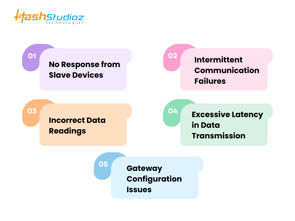
1. No Response from Slave Devices
If a Modbus RTU slave device does not respond, consider the following checks:
Possible Causes & Solutions:
- Incorrect Wiring: Ensure A (Data+) and B (Data-) lines are correctly connected. Swapped lines prevent communication.
- Missing or Incorrect Termination Resistors: RS485 networks require 120-ohm termination resistors at both ends to prevent signal reflections.
- Baud Rate Mismatch: The master (Modbus RTU Gateway) and slave devices must share the same baud rate (e.g., 9600, 19200, 38400 bps).
- Wrong Slave Address: Each Modbus RTU device needs a unique address; check the slave ID in configuration software.
- Faulty Device or Port: Swap the device or use another RS485 port to verify hardware functionality.
Tip: Use a Modbus simulator tool (e.g., ModScan, Modpoll) to check device availability.
2. Intermittent Communication Failures
Random connection failures can disrupt data exchange between Modbus RTU Gateway, RS485 IoT Gateway, and connected devices.
Possible Causes & Solutions:
- Electromagnetic Interference (EMI): Shield RS485 cables and route them away from high-voltage lines and motors to minimize interference.
- Long Cable Lengths: RS485 supports up to 1200 meters, but voltage drops and signal degradation can occur over long distances. Consider signal boosters or repeaters.
- Incorrect Network Topology: Avoid star or branching connections; use a daisy-chain configuration.
- Floating Ground Potential: Ensure all devices share a common ground reference to avoid voltage mismatches.
Tip: An oscilloscope can be used to check for noise and voltage fluctuations on the RS485 signal lines.
3. Incorrect Data Readings
If data from sensors, PLCs, or actuators appear incorrect or unstable, verify the following settings:
Possible Causes & Solutions:
- Register Mapping Errors: Cross-check the Modbus register addresses and ensure the correct offsets are used. Some devices use zero-based addressing, while others start at 1.
- Incorrect Parity Settings: Modbus RTU supports Even, Odd, or No Parity. The master and slave must have the same parity configuration.
- Mismatched Data Formats: Some devices use Big-Endian, others Little-Endian. Ensure your Modbus RTU Gateway interprets data correctly.
- Slow Polling Intervals: If data changes too quickly, reduce the polling delay to capture real-time updates.
Tip: Use Modbus debugging software to inspect data packets and verify register values.
4. Excessive Latency in Data Transmission
If the system experiences delays in data retrieval, the issue may be network congestion or improper configuration.
Possible Causes & Solutions:
- Overloaded Gateway: Reduce the number of connected devices per Modbus RTU Gateway or optimize polling intervals.
- Slow Serial Communication: Increase the baud rate (e.g., from 9600 to 38400 bps) for faster data exchange.
- Excessive Requests: Reduce unnecessary Modbus polling by configuring event-driven data requests instead of frequent queries.
- Congested Network: If using an RS485 IoT Gateway, ensure it has sufficient processing power to handle multiple protocols efficiently.
Tip: Check the Modbus RTU timeout settings and adjust them based on network response times.
5. Gateway Configuration Issues
If the Modbus RTU Gateway or RS485 IoT Gateway does not communicate as expected, incorrect settings may be the cause.
Possible Causes & Solutions:
- Mismatched Protocols: Ensure the gateway is correctly configured to convert between Modbus RTU, Modbus TCP, or MQTT as required.
- Firewall Blocking Traffic: If using Modbus TCP, ensure that port 502 is open on all relevant network devices.
- Firmware Issues: Check if the gateway firmware is up to date to prevent bugs or outdated configurations.
- Incompatible Device Settings: If the gateway supports multiple RS485 IoT devices, ensure that their communication parameters (baud rate, parity, stop bits) match the gateway settings.
Tip: Reset the gateway to factory settings and reconfigure step by step to identify misconfigurations.

Conclusion
Setting up a Modbus RTU Gateway on an RS485 network ensures seamless communication between industrial devices and modern IoT platforms. By following structured steps—selecting the right hardware, proper wiring, configuration, and testing—you can achieve an efficient and secure industrial communication setup.
FAQs
1. What is the maximum number of devices on an RS485 network?
RS485 supports up to 32 standard devices, but repeaters can extend this limit.
2. Can Modbus RTU and Modbus TCP work together?
Yes, a Modbus RTU Gateway can convert RTU signals to TCP for remote access.
3. How do I reduce interference in an RS485 network?
Use shielded twisted-pair cables, proper grounding, and termination resistors.
4. What is the typical baud rate for Modbus RTU?
Common baud rates are 9600, 19200, and 38400 bps, depending on network requirements.
5. Can RS485 IoT Gateways be used for cloud integration?
Yes, RS485 IoT Gateways support MQTT, HTTP, and cloud APIs for remote monitoring.